
Modular Block Connectors — one connector, six contact types
A rectangular industrial connector whose interior is built from modules. Signal, power, fiber optic, databus, coaxial and hydraulic all run through the same housing: where you once needed three connectors, one is now enough.
- Up to 100,000 mating cycles guaranteed with hyperboloid contacts
- Up to 14 modules per connector, 3 to 20 positions each
- IP67 on aluminum housings, IP68 on threaded hoods with EMC shielding
- DIN 43652 compliance and NF F61-030 railway certification · Made in Italy
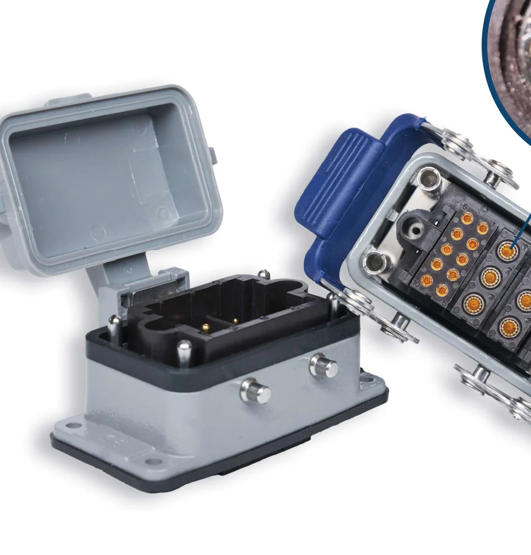
Modular means you decide what goes inside
In conventional industrial connectors the insert is fixed: the number of contacts is what it is. In the Modular Block, the housing is a frame, and you fit it with modules chosen one by one — up to fourteen, in 2, 3, 5, 7, 10 and 14-module configurations.
Each module can carry a different contact type. Signal, power, fiber optic, databus, coaxial and hydraulic coexist in the same connector: that’s the difference between one panel cutout and four, one stocked part number and four, one potential leak point and four.
Housings are available with single or dual locking systems and top or side cable entry. Custom configurations are available upon request.
In 2, 3, 5, 7, 10 and 14-module configurations. Each module has 3 to 20 positions.
Signal, power, fiber optic, databus, coaxial and hydraulic in the same housing.
From 5 A to 60 A depending on the module, with rated voltage from 63 to 630 V.
IP67 on aluminum housings, IP68 on shielded threaded hoods.
Why this connector withstands 100,000 matings
A conventional contact is a spring finger that slides against a pin: each mating wears away a little of the gold plating, until the base metal shows through and resistance rises. The hyperboloid contact works differently.
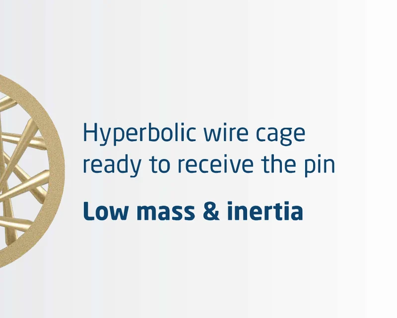
A wire cage, not a spring finger
Inside the socket is a cage of wires arranged in a hyperboloid. When the pin enters, the wires flex and wrap around it, touching it along multiple contact lines at 360° instead of at one or two points.
Insertion force stays low, and the wires exert a wiping action on the pin surface with every mating. The result stated in the catalog: over 100,000 guaranteed cycles, with consistent electrical and mechanical performance over time.
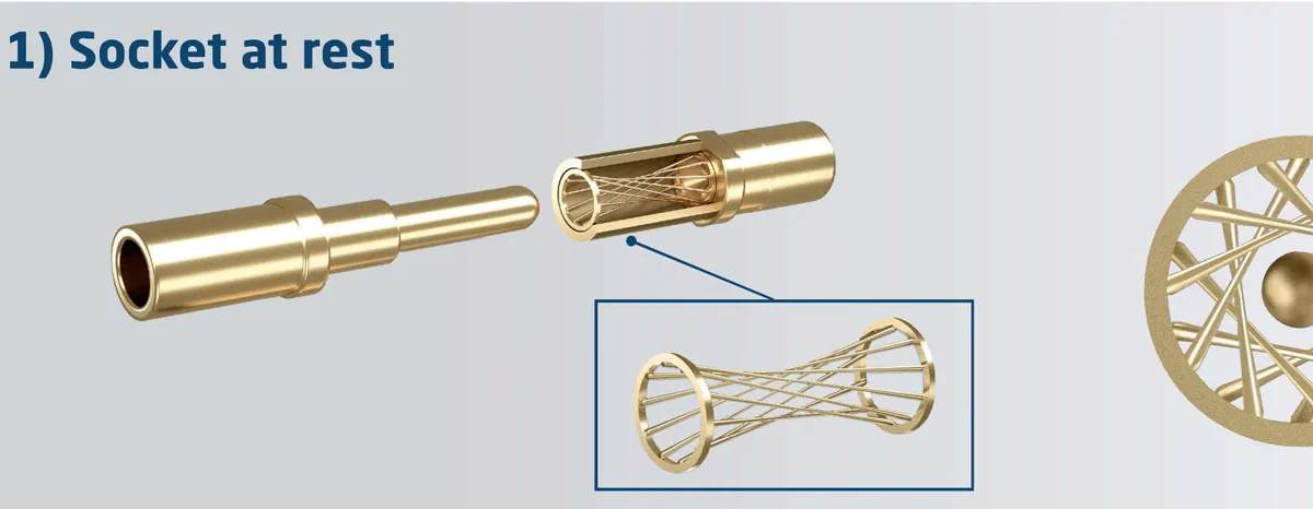
Socket at rest
The hyperbolic wire cage is ready to receive the pin. Low mass and inertia.
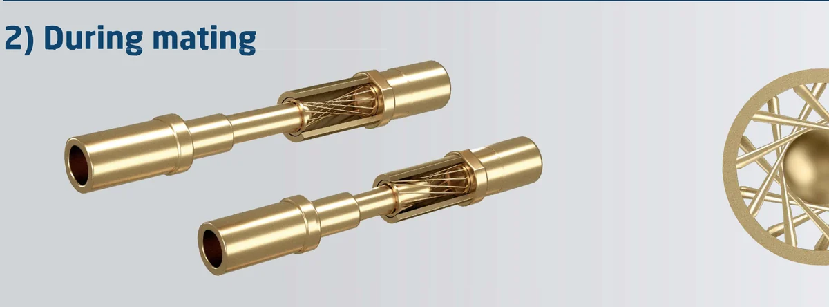
During mating
The wires flex gradually: low insertion force and a wiping action on the pin surface.
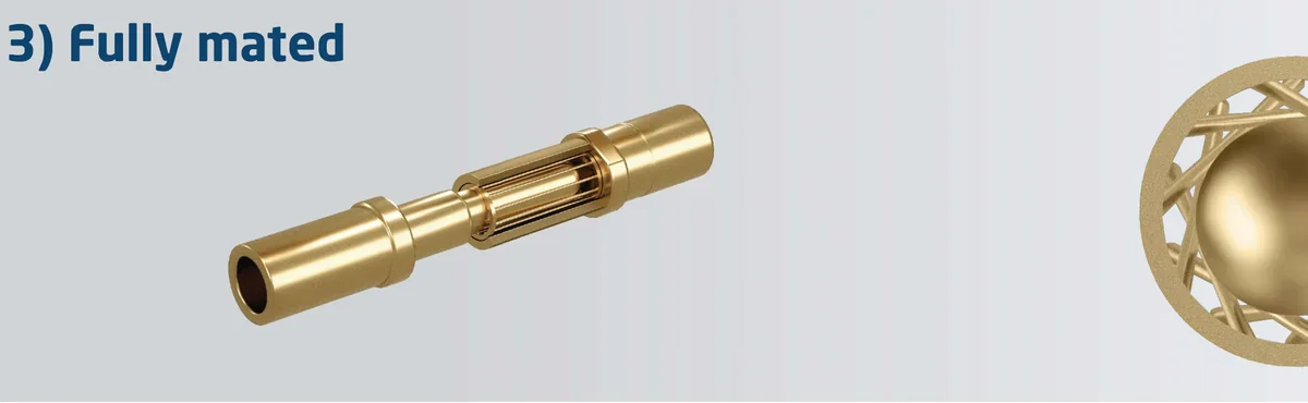
Fully mated
The pin is touched along multiple contact lines at 360°: a stable, low-resistance connection.
Sequence and descriptions from the CPE Modular Block Connectors catalog, ed. 03/2026.
Why this number matters. On a test bench, the connector is mated and unmated dozens of times a day. When the contact degrades, measurements start drifting before the part fails: the real cost isn’t the replacement part, it’s the downtime and the doubt cast on the data collected in the meantime.
The value stated in the catalog for the hyperboloid contact solution.
From 0.3 to 7.0 mΩ depending on the module, stable over time.
How the connector is built
Three choices in sequence: how many modules, which contact type in each, and which housing. Everything else — locking, cable entry, protection — depends on the application.
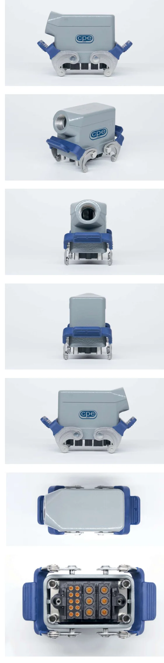
How many modules
Configurations with 2, 3, 5, 7, 10 and 14 modules per connector. Each module holds 3 to 20 positions, with nominal pin diameters from 1 to 3.5 mm.
What needs to pass through
Signal, power, fiber optic, databus, coaxial and hydraulic. Modules can be freely mixed in the same housing: this is where the product stands apart from a fixed-insert connector.
Which housing
Aluminum housings with single or dual locking systems, top or side cable entry. IP67 as standard, IP68 with threaded hoods and EMC shielding. Ruggedized options in the catalog.
If you need something else
Custom configurations are available upon request: this is where it pays to talk directly with our engineering team.
Not sure which module to start with?
Tell us what needs to pass through the connector — how many signals, how much power, whether you need fiber or coax — and we’ll propose a configuration.
Specifications stated in the catalog
The connector
| Feature | Stated value |
|---|---|
| Configurations | Up to 14 modules per connector (2, 3, 5, 7, 10, 14) |
| Positions per module | 3 to 20 |
| Housings and covers | Single or dual locking system; top or side cable entry |
| Degree of protection | IP67 on aluminum housings; IP68 on threaded hoods with EMC shielding |
| Mechanical resistance | Shock and vibration resistant; EMI/RFI shielding |
| Mating cycles | Up to 100,000 guaranteed |
| Operating temperature | −40 °C … +125 °C |
| Insulation resistance | > 10¹⁰ Ω |
| Insulator | UL94 V0 polyamide, compliant with NF-F-16102 Es.3 |
The contact
| Feature | Stated value |
|---|---|
| Contact types | Signal, power, fiber optic, databus, coaxial and hydraulic in the same connector |
| Nominal pin diameter | From 1 mm to 3.5 mm; modules with 3, 5, 10 and 20 positions |
| Current rating | From 5 A to 60 A depending on the module |
| Contact resistance | From 0.3 to 7.0 mΩ |
| Rated voltage | From 63 V to 630 V depending on the module |
| Rated impulse withstand voltage | From 1.5 to 8 kV depending on the module |
| Contact mating cycles | Up to 100,000 guaranteed |
| Material and plating | Brass, gold-plated |
Compliance and testing
| Feature | Stated value |
|---|---|
| Compliance | DIN 43652 · NF F61-030 railway certification |
| Salt spray | Minimum 96 h per MIL-STD-1344 / EIA-364-26 |
Heavy-duty industrial sectors
These are the sectors listed in the catalog under “Heavy duty industrial sectors.”
Test & Measurement
Automation & robotics
Medical electronics
R&D laboratories
Railway & transportation
Test & Measurement is the sector where the 100,000-cycle rating matters most: it’s where the connector is mated and unmated as part of the daily work cycle, not just during assembly or maintenance.
Railway. The catalog states compliance with the DIN 43652 standard and the requirements of NF F61-030. The insulator is UL94 V0 polyamide, compliant with NF-F-16102 Es.3.
The complete catalog
Four pages covering the system description, connector and contact tables, the hyperboloid contact mating sequence and applications. We only ask for your name, company and email so we know who we’re helping, and the download starts as soon as you submit.
Related products. If you have circular connectors or classic D-shaped connectors at the other end, you can use our CCB and CRB backshell families, or our heat-shrink or cold-shrink Preformed Boots.
CPE Modular Block Connectors
Modular system description, connector and contact technical tables, hyperboloid contact sequence, application sectors and CPE locations worldwide. Edition 03/2026.
Get the PDF PDF · 4 pagesWe ask for your name, company and email: the download starts as soon as you submit.
Let’s start with what needs to pass through the connector
This product isn’t chosen from a price list: it’s configured. Tell us how many signals and which types need to pass through, in what environment and how often it will be mated, and we’ll reach the right configuration in a single conversation.
- Custom configurations upon request
- An answer from an engineer within one business day
- Samples evaluated case by case
Configure your connector
Describe your application: we’ll propose the right combination of modules and housing.